5,500 gallon Rainwater Harvesting System installed near Laureles Grade in CV.
In October 2011, a 5,500 gallon rainwater harvesting system was installed by Garden Solutions Landscaping off Laureles Grade. The characteristics of this system are as follows and are based on the protocols and guidelines developed by the American Rainwater Catchment Systems Association. The ARCSA guideline is based on industry leading standards for the design and management of rainwater harvesting systems.
1) The roof catchment surface consists of over 1,250 square feet and is made of composition shingles.
2) The catchment area will yield approximately 12,700 gallons per year based on average rainfall.
3) The conveyance system included 4 downspouts placed over 100+ linear feet with approximately a 15 foot fall in elevation and installed with 3" schedule 40 PVC pipe.
4) Each downspout was mounted with a Leaf Eater Advanced filter unit to remove sediment running off the roof.
5) An 18 gallon in ground first flush was also installed to remove undesirable water prior to it flowing into the tank.
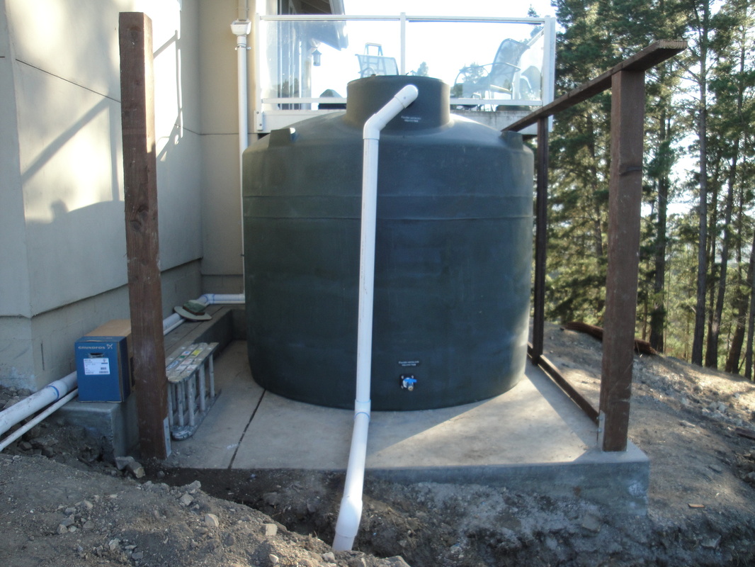
6) The 5,500 gallon system is made up of 3 tanks total. A 2,500, and two 1,500 gallon tanks which sit underneath the deck.
7) A floating extractor was installed in the 2,500 gallon tank to suction water approximately 6" below the surface of the tank where it is the cleanest.
8) Each tank is connected at the bottom with ball valves on each side plus a Falcon stainless steel flexible connector that allows for flexibility and the management of water between the tanks.
9) The overflows from tank 1 and tank 2 includes Fernco flexible fittings to allow for movement.
10) Calming inlets are used inside of tank 1 and tank 2 to reduce agitation of sediment settled at the bottom of the tanks.
11) An anti-siphon hole was drilled in the top of the calming inlet to avoid siphoning the tank back through the first flush device.
12) Skimming overflows inside tank 1 and tank 2 were used to move water between tanks.
13) Non-potable stickers were liberally used throughout the system in English and Spanish to insure nobody mistakes the water for potable!
14) The water collected will be used to irrigate landscape. The high point will be about 30 feet above the tank location. A Grundfos MQ3-45 compression pump is connected to the floating extractor and will push water throughout the irrigation field. This pump automatically senses pressure in the line and will shut off until needed. In addition the pump will shut down when water levels in the tank become depleted.
15) A mechanical tank level monitor was installed at the top of the 2,500 gallon tank to easily view the water level.
16) At the end of the overflow device a rock pit energy dissipation system was installed to avoid erosion.
Following is a montage of the design and installation of the system.
1) The roof catchment surface consists of over 1,250 square feet and is made of composition shingles.
2) The catchment area will yield approximately 12,700 gallons per year based on average rainfall.
3) The conveyance system included 4 downspouts placed over 100+ linear feet with approximately a 15 foot fall in elevation and installed with 3" schedule 40 PVC pipe.
4) Each downspout was mounted with a Leaf Eater Advanced filter unit to remove sediment running off the roof.
5) An 18 gallon in ground first flush was also installed to remove undesirable water prior to it flowing into the tank.
6) The 5,500 gallon system is made up of 3 tanks total. A 2,500, and two 1,500 gallon tanks which sit underneath the deck.
7) A floating extractor was installed in the 2,500 gallon tank to suction water approximately 6" below the surface of the tank where it is the cleanest.
8) Each tank is connected at the bottom with ball valves on each side plus a Falcon stainless steel flexible connector that allows for flexibility and the management of water between the tanks.
9) The overflows from tank 1 and tank 2 includes Fernco flexible fittings to allow for movement.
10) Calming inlets are used inside of tank 1 and tank 2 to reduce agitation of sediment settled at the bottom of the tanks.
11) An anti-siphon hole was drilled in the top of the calming inlet to avoid siphoning the tank back through the first flush device.
12) Skimming overflows inside tank 1 and tank 2 were used to move water between tanks.
13) Non-potable stickers were liberally used throughout the system in English and Spanish to insure nobody mistakes the water for potable!
14) The water collected will be used to irrigate landscape. The high point will be about 30 feet above the tank location. A Grundfos MQ3-45 compression pump is connected to the floating extractor and will push water throughout the irrigation field. This pump automatically senses pressure in the line and will shut off until needed. In addition the pump will shut down when water levels in the tank become depleted.
15) A mechanical tank level monitor was installed at the top of the 2,500 gallon tank to easily view the water level.
16) At the end of the overflow device a rock pit energy dissipation system was installed to avoid erosion.
Following is a montage of the design and installation of the system.